Hey dude, are you going to make a conversion table for temperature sensor? I have a better option! Here is automatic formula calculator for any temperature sensor. 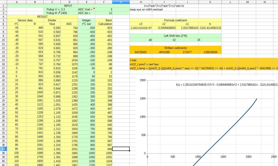
Category Archives: Electronics
Электроника и всё что с эти связано.
Battery management IC (cell monitor) overview: LTC6803, BQ76920, ISL94203
There few words i want to say about ICs passed trough my hands. I have tested by my own LTC6803, BQ76920 (BQ7694003) and ISL94203.
Linear LTC6803: Very nice IC to use, simple but engineers really think when did them, first of all, it has option to measure voltage with turned off balancing resistors. This feature is must-to-do if you want to balance battery of 12S+ to ~3mV (adc is very accurate). It has daisy-chain option so you can easy stuck up to 96 cells for example. This daisy is not stable under heavy inverter loads, it communicates through two diodes (take a look at datasheet), but if you connect adjacent ICs grounds with capacitor (100n 100V in my case), data transfer may become much more stable (this is fixed in newer LTC6804 with isoSPI interface). CRC calculation included and SPI interface. I really prefer SPI, not I2C becouse of STM32 stupid I2C controller. There are only two additional ADC inputs, sometimes this is not enough (used for t-sensor or shunt). But IC have 2 GPIO pins, you can connect a EEPROM and use this pcb as standalone battery block in large pack. Also nice package 44SSOP, good layout. Quite robust against wrong connection and such type of thing.. IC is simple, didn’t do anything without your wish (well… mostly) so it is easy to use with external MCU and quite fast to program-and-ride. Dis only one – price. 10$ at least for 12S.
Texas BQ7694003: well. this IC is cheap. ~4$ for 15 cells? huh. BUT IT HAS NO F*NG TIMEOUT RESET. What does that mean? Lets say you enabled cell balancing at the end of charge, after that your MCU sent shutdown request and goes to sleep. But, due to some magic your request is lost. Now you have 0.1V 0V 0.3V 0.4V 0V …. 0.1V battery pack. Quite a lot of money, huh? Also noted some sort of hang when power-up or connecting capacitive load to battery.. well, maybe next time i will have more fun with this ICs, not now. Layout divided on some kind of blocks in one ics, 5 cell each. Lower cell connection not so easy as on LTC6803, where whatever-you-connect-it-this-will-work-fine. Integrated current sense and FET control. But i don’t like idea of FET controlling with cell-monitor IC. If something goes wrong with FET, this IC also may be burned, so battery will be totally discharged trough balancing wires. Spend 0.2$ for external FET driver. Current protection works.. most of time.
Intersil ISL94203: sweet cheap 2-3$ ICs, timeout protection, standalone capable, FET driver, two ICs on one bus possible (address pin). Just connect VBAT through not-more-than 47R resistor to avoid adc values drop. Low accuracy, no auto balancing turn-off when measure cells, so you have to do this by your own. There is no CRC 😦 dummy-dummy read is your way. Hard to configure, a lot of registers and functionality that you don’t need if using with external MCU. Not so robust against ‘oops i dropped this wire on pcb’ as LTC. And you can’t start all-cells conversion by click. Only automatic way or byte-by-byte. So you have to play around to get similar functionality as LTC, if you need better voltage readings.
TIPS: – CASC mode does not work for ADDR=0, use low threshold EOC and CB_EOC=1 for balancing with MCU.
– synchronize SCAN for dual IC design, to get proper readings and disable balancing when you make SCAN.
Intersil ISL94212 (not truly tested yet): just in case you need daisy-chain and moar cells to measure with low price (5-7$). SPI, capacitive daisy should work much better in case you have connected something wrong, but i think this will meet same problems with communication as LTC6803. Not so cool package.. square. 4(!) external t-sensors, that’s good. CRC for daisy chain and timeout, also very good. Same accuracy as 203 but should be easer to control, as this IC is works only with MCU. Looks almost same as LTC, but twice less price. I should really test them!
Motor-controller test bench
Yeah! Finally! Now i can measure parameters of any motor and debug the controller much easier.

BLDC Back EMF Integration #2
In a previous article i was suprised by difference in BEMF signals, now i’ve got new PCB, reworked code, and made some investigation
BLDC Back EMF integration understanding #1
Most of documents about this article show two basic formula –
For PWM off time – Vphase = 3/2*e
For PWM on time – Vphase = 3/2*e + Vdc/2
And show us beautiful voltage waveforms with PWMed BEMF, where ON and OFF time parallel. But i have another situation with mine 8kW hub-motor. Look at this:

Typical examle, where off-time BEMF differs from on-time on Vdc/2. Here’s mine:
Second PWM cycle inverted. Green area- affected by diode, integration starts in red area, after zero crossing. Closer view:


At the beginning of the cycle is seen resonant oscillations, for my motor they lasts about 10uS, ADC samples in center of ON time and OFF time, what give us clear data, without interference.
What is source of this mis-alignment? For proper BEMF integration i should take phase voltage, subtract neutral point, and integrate the resulting value. For off-time it is right, if we take neutral point as zero, coz other two phases on the ground, resultant step-switch very accurate with installed hall sensors. But if i take raw value from on-time, subtract Vdc/2, voltage is incorrect, step-switch comes too early. This means neutral point moves with BEMF, actually it is always moves, coz of third harmonic, but this is seen only when two other phases is powered.
UPD1: Finally i’ve got this:

I had to make current spike detector, you can see on BEMF graph filtered and real value BEMFs. Only this way high inductance motors run fine under load.
LiFePO4. Безопасность.
В предыдущем посте я оговаривал причины выбора LiFePO4 аккумулятора, и одним из аргументов было то что его можно проткнуть гвоздем, и ничего страшного не произойдет. Вот хороший видос на эту тему:
Кромсаем LiFePO4 баттарейку
UPD:
А вот видео от отечественного эксперементатора 🙂 если кажется что первое – фейк.
E-Bike. Inception.
Спустя 4 месяца у меня дошли руки сдуть пыль и паутину со своего “скромного блога” и запостить фоточки в инстаграм описать то чем я занимался все это время. Чтож, начнем..

Управление MOSFET-ами #1
В инете полно статей о том как работают MOSFET-ы (ака полевики, т.е. полевые транзисторы), что надо рулить напряжением а не током. Разберем поподробнее + и – разных драйверов.

